The model is the toolpath.
- Features are the building blocks. You build a part by adding and subtracting 2D shapes — rectangles, circles, polygons, imported curves — in the Sketch view. Each shape is a feature.
- Top Z and Bottom Z define the 3D shape. Every feature has a vertical extent. Top Z is where the feature starts (the surface) and Bottom Z is where it ends (the floor). These same values directly control how deep machining operations cut — there are no separate depth fields to set.
- Feature type determines which operations apply. An additive feature represents material that is present (e.g., a raised boss). A subtractive feature represents material that is removed (e.g., a pocket). The available operation types — pocket, contour, facing — adapt accordingly.
- Features can be combined. Overlapping features are merged into composite shapes. You can also resize, move, and re-order features at any time; the model and toolpaths update to reflect the change.
- Order matters. Features are applied in the order they appear in the feature tree — top to bottom. You can reorder them by dragging. The first feature must always be an additive one (it defines the base material to work from); the app marks it with a lock icon to indicate it cannot be moved below any subtractive feature.
- Visibility drives calculation. Making an operation visible in the feature tree is what triggers its toolpath to be computed and shown in the 3D view. There is no separate Compute button.
Create a new project
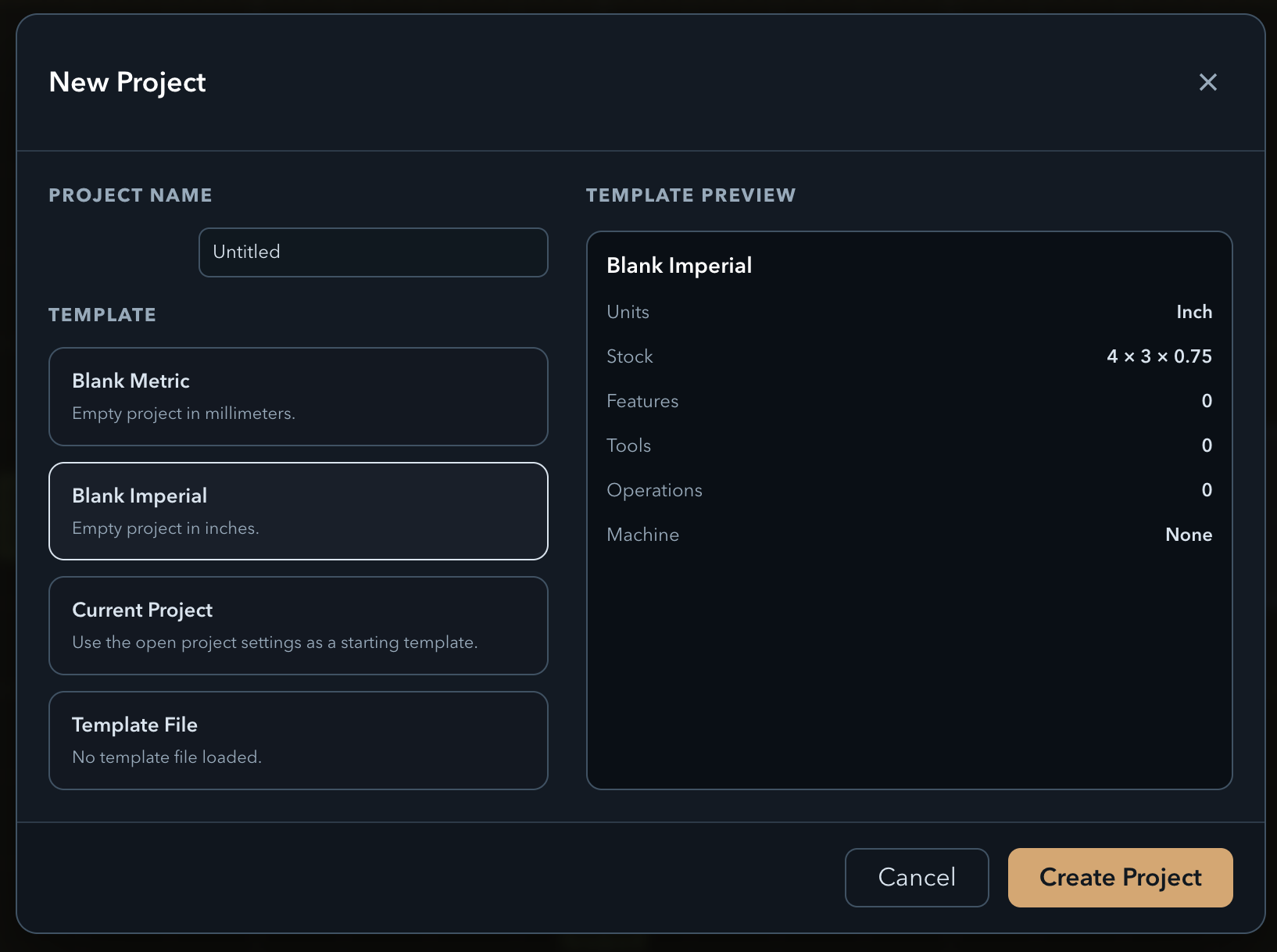
↑ topOpen PureCut CNC and click New Project. The dialog asks for a project name and a template. Select the Blank Imperial template ("Empty project in inches.") — the preview on the right confirms Units: Inch and a default Stock of 4 × 3 × 0.75. Click Create Project.
You land on the Sketch view with an empty canvas and a feature tree on the left. The default stock Top Z of 0.75 in is inherited by any features you create.
Add the outer boundary rectangle
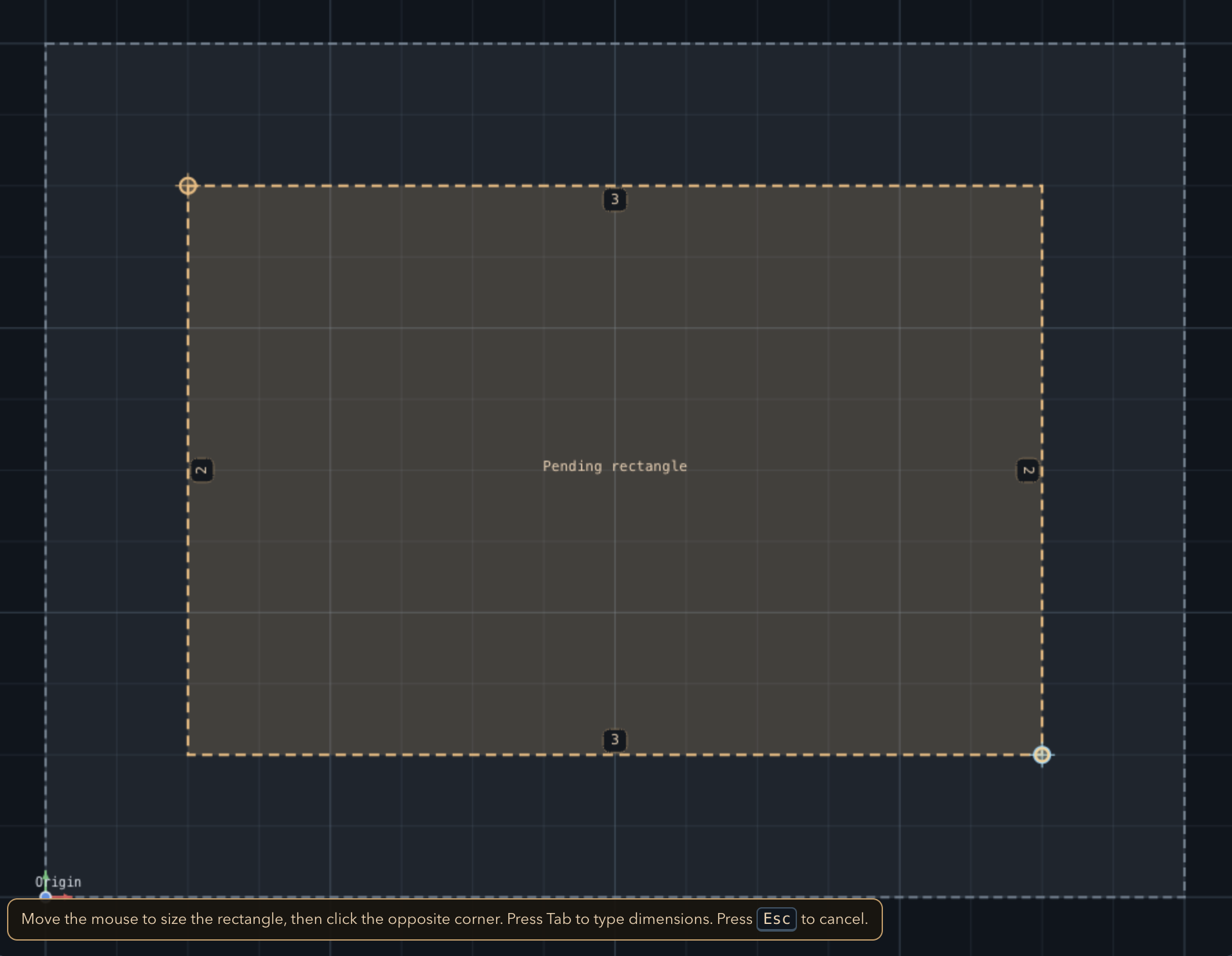
↑ topIn the toolbar, click the Rectangle tool. Click once on the canvas to place the first corner, then click again to set the opposite corner. Use the dimension inputs to lock the size to an exact value — for example, 4 × 3 inches.
This rectangle defines the outer boundary of the model. Once placed, it appears as a feature in the tree. You can click it to select it and edit its dimensions in the properties panel at any time.
Add a circle inside the rectangle
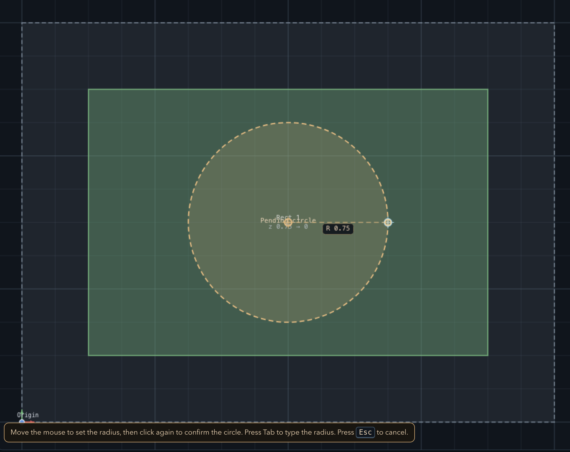
↑ topSelect the Circle tool. Click the center of the rectangle to place the origin, then drag outward to set the radius. A 1-inch radius works well inside a 4 × 3 boundary.
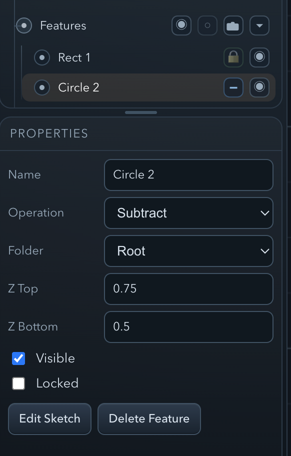
With the circle selected, open its properties panel. The Top Z will already be set to 0.75 in (inherited from the stock). Set the Bottom Z field to 0.5 in. This means the floor of the pocket sits at 0.5 in — a cut depth of 0.75 − 0.5 = 0.25 in.
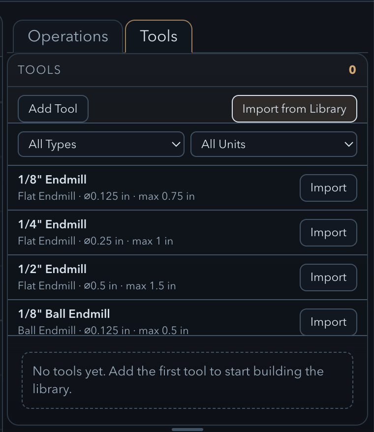
Import a 1/4″ end mill from the tool library
↑ topClick the Tools tab in the right-hand panel, then click Import from Library. The library dialog shows a catalogue of common bit profiles organized by type and diameter.
Locate the 1/4″ Flat End Mill entry and click Import. The tool is now available in the project's tool list and can be assigned to any operation.
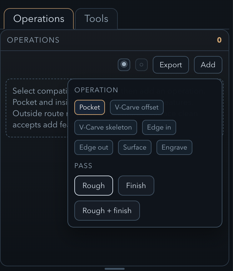
Create a rough pocket operation
↑ topSelect the circle in the feature tree (or on the canvas), then click Add in the Operations panel. From the operation type dropdown, choose Pocket Rough.
In the operation settings, assign the 1/4″ End Mill you just imported. Review the default stepover and stepdown values — the app pre-fills sensible defaults based on the tool diameter. Leave them as-is for this walkthrough.
To calculate the toolpath and see it in the 3D view, make the operation visible by toggling its visibility icon in the feature tree. The toolpath is computed automatically whenever the operation is visible.
Preview the toolpath
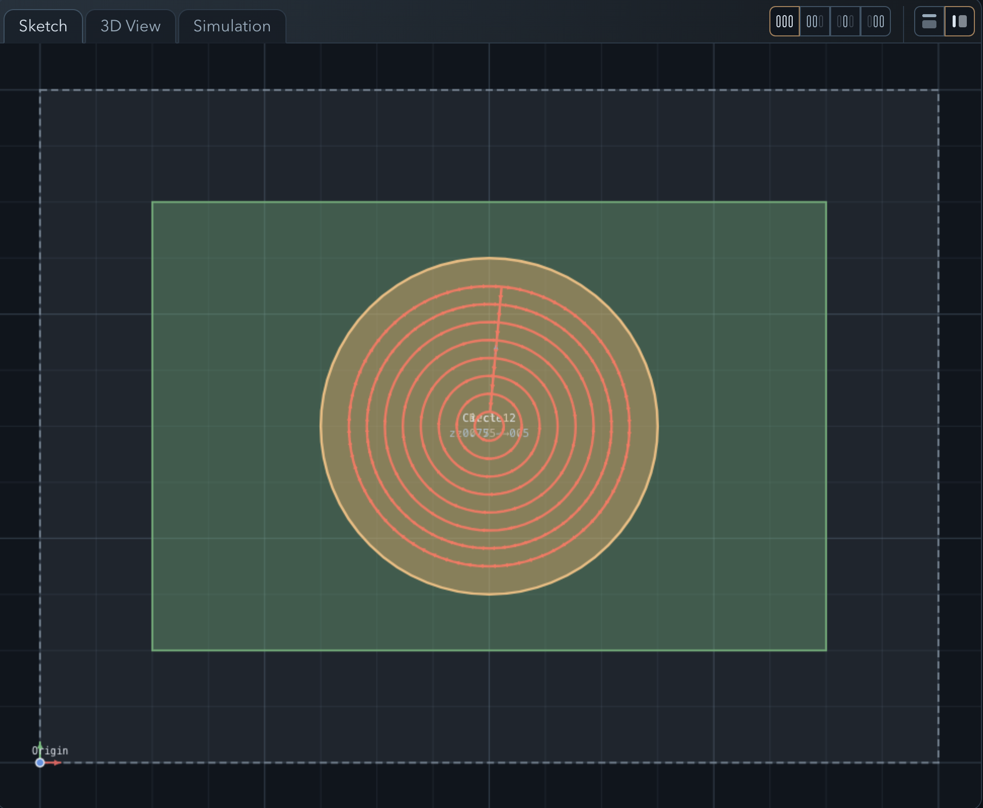
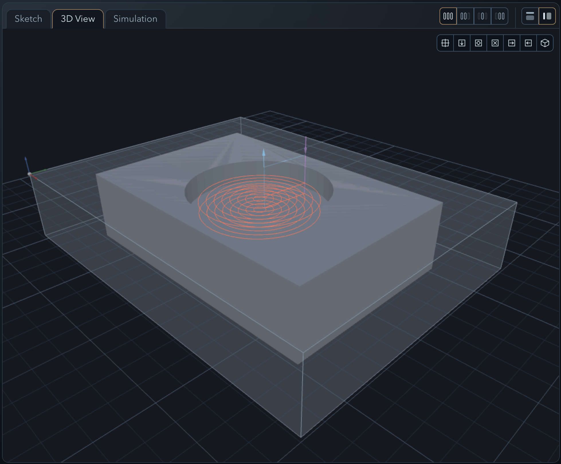
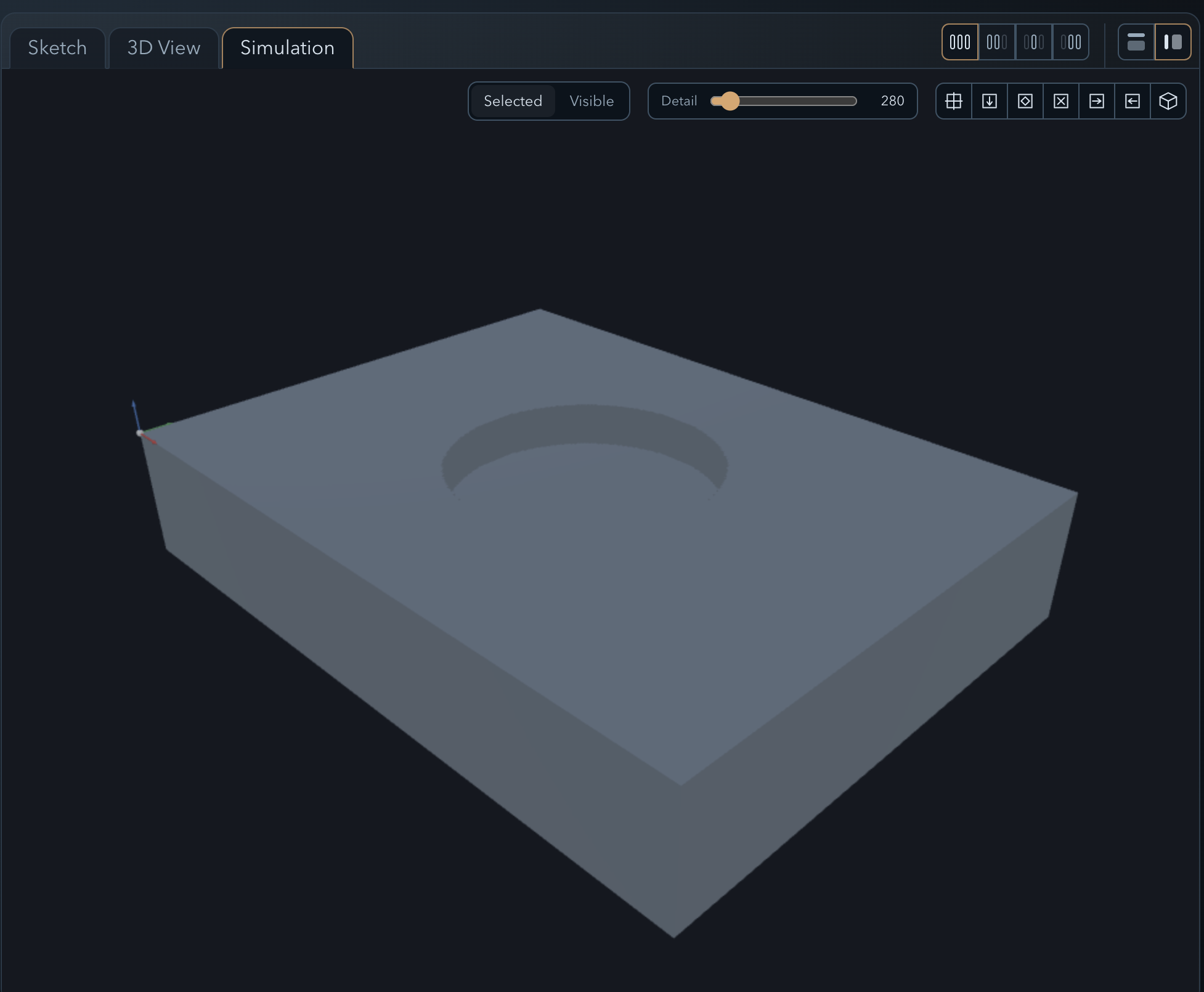
↑ topThe workspace has three tabs — Sketch, 3D View, and Simulation — and you can switch between them freely at any point.
In Sketch you can still see the geometry and the feature tree, and go back to tweak any feature or operation parameter. In 3D View the pocket toolpath renders as colored lines over the stock block — rapid moves in one color, cutting passes in another. Use the mouse to orbit, zoom, and pan to inspect the path from any angle. In Simulation you can watch the tool move through the material and see the machined result.
If anything looks wrong — unexpected depth, toolpath outside the boundary, missed area — switch back to Sketch, adjust the feature or operation, and the toolpath will recompute automatically.
Select a machine and export G-code
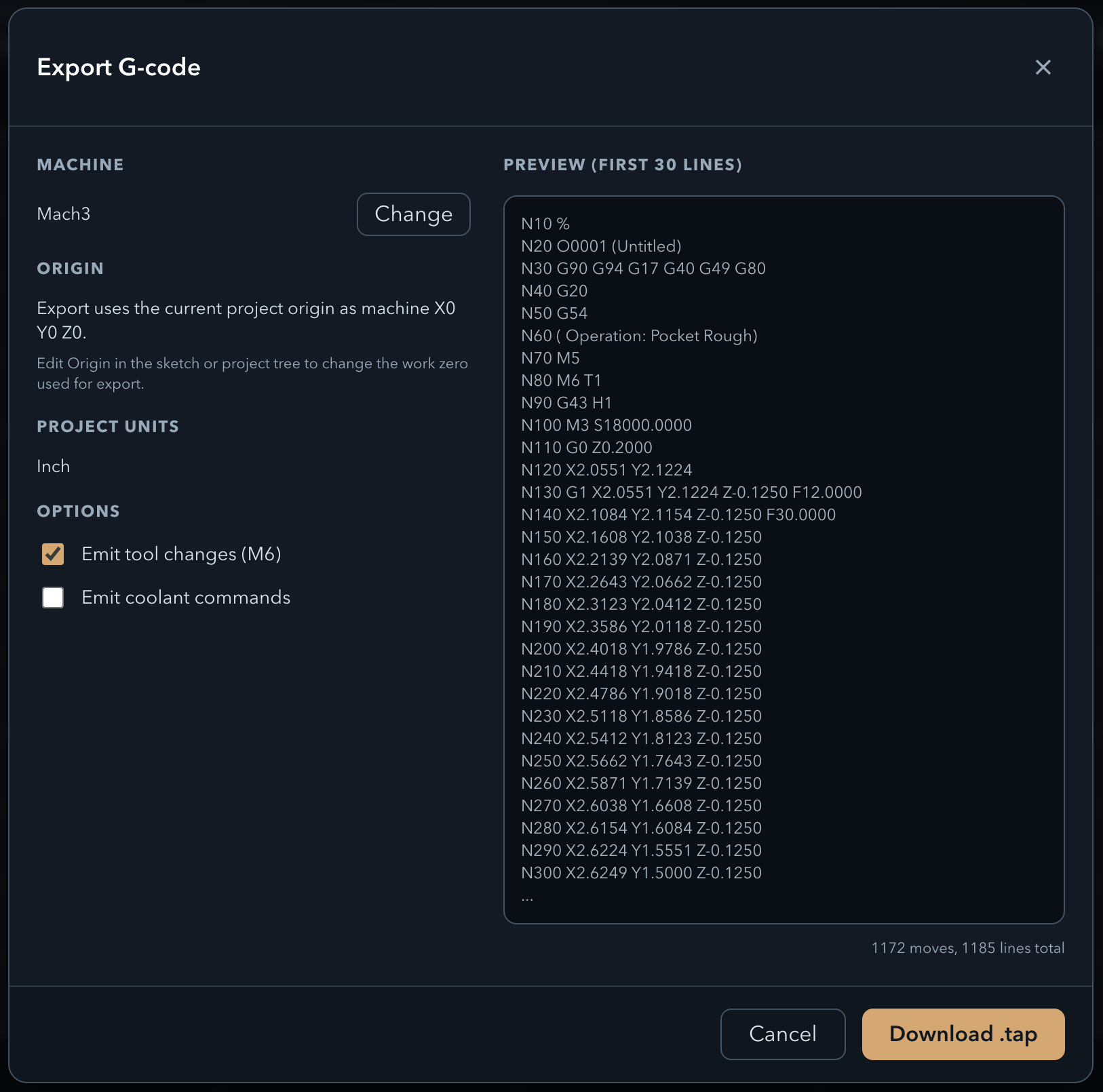
↑ topIn the feature tree, click the top-level Project entry to open the project properties panel. Find the Machine dropdown and select Mach3. This sets the post-processor; PureCut CNC will format the output with the dialect, units, and header/footer that Mach3 expects.
Click Export G-code. The browser downloads a file ready to load directly into Mach3. Open it in a text editor to review the output before running it on your machine.
Now let's see if you were paying attention. 🎯
You've got a project with a rough pocket operation on the circle. Here are a few things to try on your own — each one builds on what you just learned.
- 1 Leave some material. Edit the Pocket Rough operation and set a radial and axial stock-to-leave value, so the finish pass has something to clean up.
- 2 Add a finish pass. Create a Pocket Finish operation on the same circle to clean up the floor and walls to final size.
- 3 Route the outside rough. Select the outer rectangle and add an Edge route outside Rough operation to rough-cut the part boundary.
- 4 Route the outside finish. Add an Edge route outside Finish operation on the same rectangle to bring the perimeter to final dimension.
- 5 Add tabs so the part doesn't fly off. Select the edge route operation and use the Auto place tabs button in the operation properties to let the app place them automatically — or add them manually from the project tree.
- 6 Add clamps on the left and right. Use the clamp options in the project tree to place clamps on both sides of the stock. Set their Top Z to 1 in so the tool clears them on rapid moves.